Difference between revisions of "Reverse battery or DC polarity protection"
| Line 20: | Line 20: | ||
[[File:CB radio blown trace.png|Reverse polarity protection]] | [[File:CB radio blown trace.png|Reverse polarity protection]] | ||
There was no fuse; additionally, the excessive current flowed across a whole board, up a connector, and back fully across a second board before finding the reverse diode! This is the mayhem that resulted: | |||
Revision as of 18:55, 28 December 2012
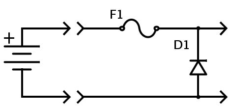
Engineers often pick this as their reverse battery or DC supply protection feature:
This method is picked because it is cheapest and least lossy. I will discuss more appropriate methods later.
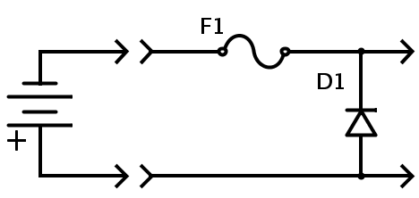
Diode D1 does not do anything, and does not waste any power on all of those occasions that the power is applied correctly. However, if the polarity is reversed:
Then diode D1 conducts, and blows out the fuse.
That would keep the device protected. However, I came across a device recently which used a PCB trace for the fuse!
I forgot the convention that the white stripe on a power cord connects to the center conductor of a DC "barrel" style connector.
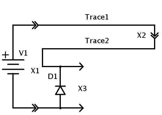
When I opened up my Cobra handheld CB radio, I have discovered that this is what they used for their protection:
There was no fuse; additionally, the excessive current flowed across a whole board, up a connector, and back fully across a second board before finding the reverse diode! This is the mayhem that resulted:


